
Chute, hopper and silo 3D scanning
A transfer chute wears from the inside, a hopper builds up where the flow stalls, a silo’s internal geometry decides whether it discharges — and none of it can be measured from outside. Inspection is a confined-space entry in a shutdown, with a torch and a tape.
A scanner through the inspection hatch records the internal surface at 1.9 mm from a tripod or 0.1 mm handheld; wear, build-up and the true geometry come out as a model the liner order or the redesign is made from.
How are chutes, hoppers and silos measured inside?
A scanner through the inspection hatch records the interior at 1.9 mm from a tripod or 0.1 mm by hand: liner wear, build-up and the true geometry as a model.
 Through the hatchThe interior recorded from the inspection opening; entry reduced or removed.
 Liner wear mappedThis scan against the last, or against the drawing: remaining thickness everywhere.
 Build-up seenWhere material has stuck and how much, before it stalls the flow.
 A redesign that fitsThe true internal geometry into CAD for new liners or a new chute.
Why chute wear is found by the hole
Inspecting a chute or a hopper means a confined-space entry: isolation, a permit, a standby, and someone inside with a torch looking at liners and tapping plate. Wear is judged by eye and, where a gauge can reach, measured at a few points. Build-up is described, not measured. And because the entry is expensive and the window is short, the inspection happens less often than the wear rate would justify — which is why the first hard evidence of a worn-through liner is a hole, spillage and an unplanned stop.
Redesign has the same problem. A chute that spills, a hopper that rat-holes or a silo that will not discharge needs a new internal geometry designed against the old one, and the old one exists only as a drawing that predates twenty years of liner replacements and field modifications. The new chute is designed from that drawing and fitted on site, with the usual result.
A scanner through the hatch records the interior. Artec Ray II on a tripod at the opening captures the whole internal surface at 1.9 mm at 10 m in under two minutes; Artec Leo, handheld through the hatch or during a short entry, records liner detail at 0.1 mm. Compared with the last scan or with the drawing in Artec Studio, wear is remaining thickness everywhere and build-up is a measured volume. The internal geometry goes into CAD for new liners or a new chute designed against what is actually there.
From hatch to liner order
The interior is captured in the time the hatch is open.
- 1. Open the hatchWith the chute or silo isolated and emptied, the inspection opening is the way in for the scanner.
 2. Scan the interiorRay II on a tripod at the hatch for the whole interior; Leo by hand for liner detail, in minutes.
 3. RegisterArtec Studio aligns the captures into one internal model on the plant’s coordinates.
- 4. CompareAgainst the last scan or the drawing: remaining liner thickness, build-up volume, wear concentration.
- 5. Order or redesignLiner geometry to the supplier; the true internal shape into CAD for a redesign that fits first time.
Which scanner for this work
The interior is captured from the hatch; the liner detail is captured by hand. Two scanners, one model.
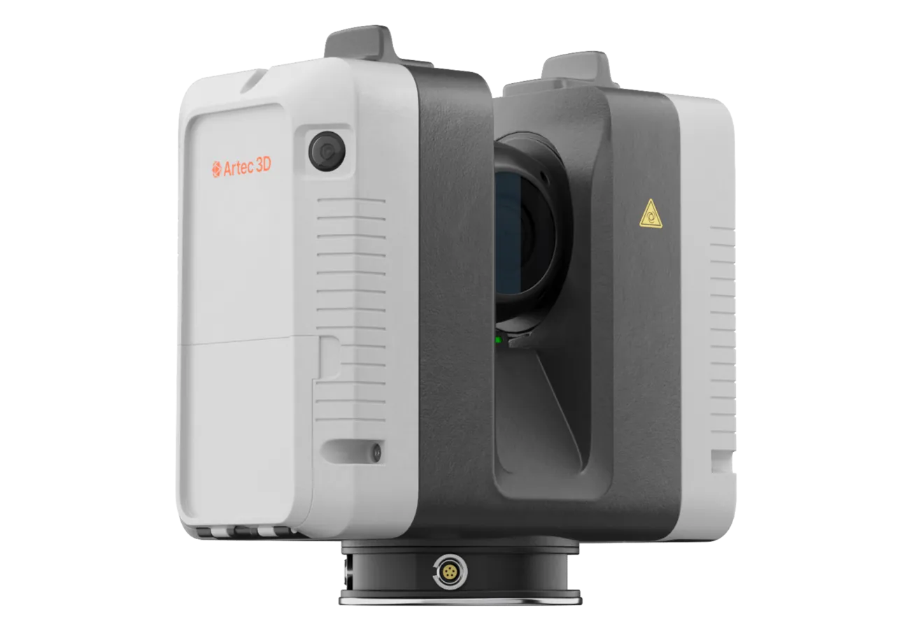
Artec Ray II
- Best for
- The whole interior from the inspection hatch, at 1.9 mm
- Type
- Stationary long-range laser, tripod mounted
- Accuracy, up to
- 1.9 mm at 10 m, 2.9 mm at 20 m, 5.3 mm at 40 m
- Range noise
- 0.4 mm at 10 m
- Range
- 0.5–130 m
- Scan time
- 1 min 42 s at 3 mm, 10 m, without texture
- Field of view
- 360° × 300°
Ray II on a tripod at the opening records the entire internal surface in one 360° × 300° station of under two minutes, at 1.9 mm at 10 m, in the dark. That gives the geometry of a chute, hopper or silo without a person inside it, and the shape a redesign is made against.
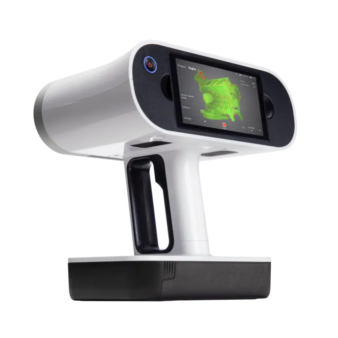
Artec Leo
- Best for
- Liner plates, wear ledges and build-up at 0.1 mm, by hand
- Type
- Wireless handheld structured light, all-in-one
- 3D point accuracy, up to
- 0.1 mm
- 3D resolution, up to
- 0.2 mm
- Working distance
- 0.35–1.2 m
- Capture speed
- Up to 35,000,000 points/s in HD Mode
- Onboard
- 5.5″ touchscreen, processing and 512 GB — no laptop
Leo, wireless and with its screen onboard, records liner detail at 0.1 mm through the hatch or during a short entry. Its HD Mode handles wet, dark and reflective liner surfaces, and the detail registers into the Ray II interior so remaining thickness is measured across every plate.
See a transfer chute’s liners mapped for remaining thickness from a scan through the hatch, with the liner order generated from the model — book a demo for your maintenance planner.
Book a demoQuestions maintenance planners ask
Does this remove the confined-space entry?
For the survey, largely: Ray II records the interior from the hatch. A short entry for Leo detail may still be wanted on critical liners, but it is minutes for a capture rather than the time a manual inspection takes.
How is remaining liner thickness measured?
By comparing the scanned liner surface with the previous scan or with the installed geometry from the drawing. The difference, at 0.1 mm on Leo detail, is remaining thickness across every plate rather than at the points a gauge reached.
Can it measure build-up in a hopper or silo?
Build-up is a surface in the scan; against the clean interior geometry it is a volume with a location. That is what tells you where the flow is stalling before it stops.
Can we design a new chute from the scan?
That is the main use. The internal geometry exports as a mesh into CAD, and the new chute or the new liner set is designed against what exists, then clash-checked against the surrounding plant in the same model.
Related applications

Tell us about the chutes and silos you inspect
Describe the equipment, the inspection interval and what fails. A mining specialist will come back with how the interior would be captured from the hatch and what the wear map would show.