Processing plant 3D scanning and as-built documentation
A processing plant is never quite the drawing. Decades of modifications, temporary fixes that became permanent and pipe runs re-routed in a shutdown have produced a plant whose only accurate record is the plant itself. Every modification starts by measuring it again, by hand.
Scanned from a tripod, the whole plant is a measured as-built at 1.9 mm at 10 m — floors, steel, pipework and equipment in one model — captured in the shutdown window and reused for every job that follows.

What does a 3D scan of a processing plant give you?
A measured as-built at 1.9 mm at 10 m — floors, structures, pipework and equipment in one model — captured in the shutdown and reused for every retrofit.
The plant as it standsAn as-built of what is there, not of what was drawn.
One hour, not sixA copper plant floor captured in one hour that took three to six by hand.
Fitted in CADEvery modification designed against the as-built and clash-checked before fabrication.
Measured laterThe next job measures the model, not the plant.
Why every plant job starts with a tape
The engineering record of a processing plant is a set of drawings that were accurate when the plant was commissioned. Since then, every shutdown has changed something — a pump swapped for a different model, a pipe run re-routed around a new platform, a conduit added where it fitted — and most of those changes were never drawn. So a new modification cannot be designed from the drawings, and an engineer goes to site with a tape, a level and a camera to measure the area concerned in the hours the shutdown allows.
Titan Engineered Solutions, who build platforms, floors and pipe runs for remote mine sites, described the consequence: engineers travelled to site to measure by hand, designed and fabricated from those measurements, and then travelled again when an unforeseen obstacle stopped the new steel from fitting. Each return trip is fabrication rework, a second shutdown window and a remote site visit.
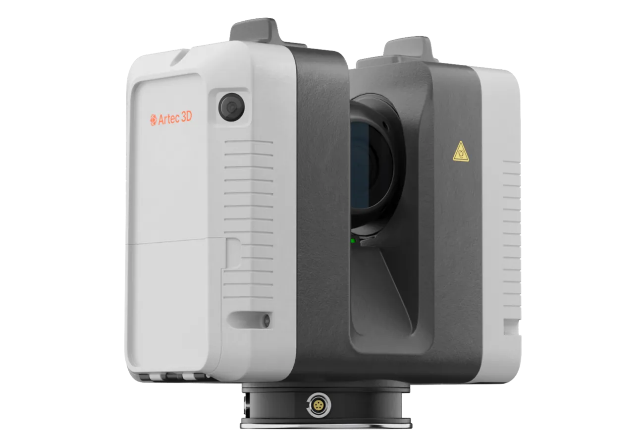
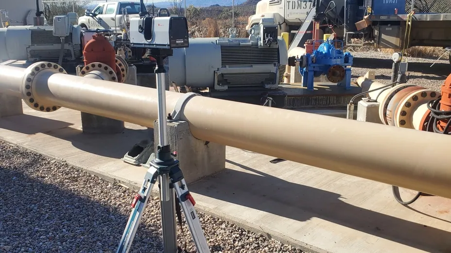
A scanned as-built ends the cycle. Artec Ray II records a plant area from a tripod at 1.9 mm at 10 m in under two minutes per station — Titan captured a copper plant floor in one hour that had taken three to six hours by hand. Artec Leo adds the tie-in detail at 0.1 mm where a flange or a bracket decides the fit. Registered in Artec Studio, the model is the as-built the modification is designed against in Geomagic Design X and SOLIDWORKS; Titan’s custom one-off pipes now meet end to end within 1.6 mm, and they report 66% less time returning to site to correct design errors.
From shutdown window to reusable as-built
The capture fits the window; the model outlives it.
1. Scan the areaRay II on a tripod at stations around the plant area, each a full 360° × 300° capture in under two minutes.
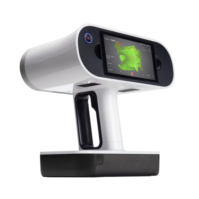
2. Capture the tie-insLeo on the flanges, brackets and nozzles the new work has to meet, at 0.1 mm, wirelessly.
3. RegisterArtec Studio aligns the stations and the detail scans into one as-built on plant coordinates.
4. Design against itThe as-built into Geomagic Design X and SOLIDWORKS; the modification designed and clash-checked in CAD.
5. Keep itThe as-built is the plant record; the next modification measures the model instead of the plant.
Which scanner for this work
A plant is large and its tie-ins are small: a tripod scanner for the first, a handheld for the second, registered together.

Artec Ray II
- Best for
- The plant area — floors, steel, pipe runs and equipment in one as-built
- Type
- Stationary long-range laser, tripod mounted
- Accuracy, up to
- 1.9 mm at 10 m, 2.9 mm at 20 m, 5.3 mm at 40 m
- Range noise
- 0.4 mm at 10 m
- Range
- 0.5–130 m
- Scan time
- 1 min 42 s at 3 mm, 10 m, without texture
- Field of view
- 360° × 300°
Ray II records a plant area from a tripod at 1.9 mm at 10 m in under two minutes per station, with a 360° × 300° view that takes in floor, structure and services overhead together. It is indifferent to lighting, so a dark mill building scans like an open floor. This is the scanner Titan used for the plant-scale capture.

Artec Leo
- Best for
- Tie-in points — flanges, brackets, nozzles — at 0.1 mm
- Type
- Wireless handheld structured light, all-in-one
- 3D point accuracy, up to
- 0.1 mm
- 3D resolution, up to
- 0.2 mm
- Working distance
- 0.35–1.2 m
- Capture speed
- Up to 35,000,000 points/s in HD Mode
- Onboard
- 5.5″ touchscreen, processing and 512 GB — no laptop
Leo records the components a modification has to meet at 0.1 mm, wirelessly and with its screen and processing onboard, so an engineer on a gantry carries nothing else. The detail scans register into the Ray II as-built in Artec Studio, which is how a pipe run designed from the model meets end to end within 1.6 mm.
Done on a real plant

“We can use the dimensions gained from a 3D scan to customize the piece and have it fit within a 16th of an inch (1.6 mm) accuracy. We do a lot of custom one-off pipes that meet end-to-end. Now we can ensure they fit without multiple tedious manual measurements.”
See a plant floor captured in an hour and a new pipe run fitted to it in CAD before fabrication — book a demo for your plant engineers.
Book a demoQuestions plant engineers ask
How much of the plant do we scan?
The area the work concerns, plus whatever the shutdown window allows. Ray II stations take under two minutes, so a plant area is a few hours and a full plant is a programme of shutdowns — each area joining the as-built as it is captured.
Does the plant have to be stopped?
Running equipment vibrates and moving parts blur, so the capture is best in a shutdown. Static structure, pipework and floors can be scanned while the plant runs where access allows; the scanner works from a tripod at a safe stand-off.
What accuracy does a retrofit need, and does the scan meet it?
Titan reports custom one-off pipes meeting end to end within 1.6 mm, designed from scans. Ray II holds 1.9 mm at 10 m on the plant and Leo 0.1 mm on the tie-ins, which is the combination that gets there.
Which CAD does the as-built go into?
Artec Studio exports standard meshes and E57 point clouds, and the Titan workflow runs Artec Studio into Geomagic Design X for deviation analysis and SOLIDWORKS for the finished part. Any CAD that reads a mesh or a point cloud can design against the as-built.
Related applications

Tell us about the plant area you need as-built
Describe the plant, the modification and the shutdown window. A mining specialist will come back with how the capture would fit the window and how the as-built lands in your CAD.