
Mine topographic survey and digital terrain models
Every plan, drainage design, rehabilitation estimate and reconciliation on the mine sits on a topographic surface — and the surface is usually a patchwork: an aerial survey from a few years ago, GNSS pick-ups where things changed, a design surface where nobody has surveyed since it was built.
A scanned topography is measured everywhere it matters: faces and structures from a tripod at survey-grade, floors, roads and dumps from a vehicle, all on mine grid and current to the week the model is built.
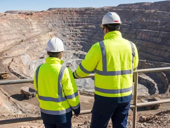
How is a mine topographic survey done with 3D scanners?
Faces and structures are scanned from a tripod at 1.9 mm at 10 m, floors and roads from a vehicle at ±15 mm; Artec Twins builds one DTM on mine grid.
 On mine gridEvery scan georeferenced with GNSS and control into one site coordinate system.
 Survey-grade where it countsFaces, structures and stockpiles at 1.9 mm at 10 m from a tripod.
 Covered where it is largeFloors, roads and dumps at ±15 mm from a vehicle, kilometres in a shift.
 Current, not historicalA DTM as of this week, rebuilt as often as the site changes.
Why the site model is older than the site
A mine topographic model is expensive to refresh, so it is refreshed rarely. An aerial or drone photogrammetry survey gives the whole site at a point in time; between flights, GNSS pick-ups patch in the areas that changed, and the parts of the site that nobody surveyed keep the surface from the last flight or, worse, the design. Drainage is designed against a topography that has since been dumped over; a rehabilitation estimate uses a dump surface from before the last three lifts; a haul road appears in the model where it was planned rather than where it was built.
Photogrammetry also struggles exactly where a mine is hardest: steep faces in shadow, bare dark rock with no texture, water, dust and the vegetation edge. The model is best on the flat, textured ground and weakest on the pit walls, which are the surfaces the geotechnical and design teams care most about.
Scanned topography is measured directly. Artec Ray II from a tripod records faces, structures and stockpiles at 1.9 mm at 10 m regardless of shadow or texture, out to 130 m; Artec Jet on a vehicle records floors, roads, ramps and dump tops at ±15 mm as it drives them, kilometres in a shift. Artec Twins georeferences everything on mine grid with GNSS and control and builds one digital terrain model, current to the week, which exports as LAS, LAZ or E57 into Vulcan, Surpac, Deswik or Leapfrog.
From scans to a current DTM
Faces from a tripod, areas from a vehicle, one model out.
 1. Scan faces and structuresRay II stations on pit walls, dump faces, stockpiles and infrastructure at 1.9 mm at 10 m.
- 2. Drive the areasJet on a vehicle records floors, ramps, roads and dump tops at ±15 mm along every drivable route.
- 3. GeoreferenceTwins registers all captures on mine grid with GNSS and the site’s survey control.
 4. Build the DTMVehicles and vegetation removed; the ground surface meshed into a digital terrain model with contours.
 5. ExportLAS, LAZ, E57 and meshes into Vulcan, Surpac, Deswik or Leapfrog as the current site topography.
Which scanner for this work
Topography needs two things: survey-grade on the faces and structures, and coverage across the areas.
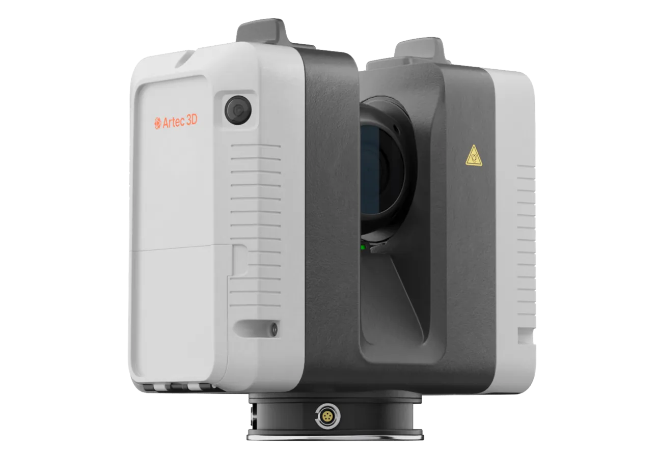
Artec Ray II
- Best for
- Faces, structures and stockpiles — the parts of the DTM that carry design and volume decisions
- Type
- Stationary long-range laser, tripod mounted
- Accuracy, up to
- 1.9 mm at 10 m, 2.9 mm at 20 m, 5.3 mm at 40 m
- Range noise
- 0.4 mm at 10 m
- Range
- 0.5–130 m
- Scan time
- 1 min 42 s at 3 mm, 10 m, without texture
- Field of view
- 360° × 300°
Ray II records a pit wall, a dump face or a plant from a tripod at 1.9 mm at 10 m and 5.3 mm at 40 m, out to 130 m, in under two minutes per station, unaffected by shadow or texture. These are the surfaces a photogrammetry model is weakest on and the ones the DTM is used for most.
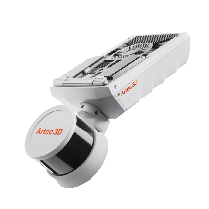
Artec Jet
- Best for
- Floors, ramps, roads and dump tops — the area of the site, from a vehicle
- Type
- Multi-modal SLAM LiDAR
- Accuracy, up to
- ±10 mm underground, ±15 mm general
- Change detection
- ±5 mm
- Range
- 0.5–300 m
- Positional drift
- ±0.03%
- Deployment
- Handheld, backpack, pole, drone, vehicle, cage, robot
Jet on a vehicle records the ground at ±15 mm along every drivable route without stopping, with 16 hours of onboard capture, so the area of a large site is covered in a shift. It registers into the same Twins model as the Ray II stations, which is what makes the DTM measured everywhere.
See a current DTM of a pit, its dumps and its roads built from scans taken this week, on mine grid and in your planning package — book a demo for your survey manager.
Book a demoQuestions surveyors ask
How does this compare with drone photogrammetry?
Photogrammetry covers a whole site quickly and is good on textured, well-lit ground; it is weakest on steep, shadowed, textureless faces — the pit walls. Scanning measures those faces directly at 1.9 mm at 10 m, and covers the areas from a vehicle. Many sites use both, with the scan model as the reference.
How often can the DTM be rebuilt?
As often as the faces are scanned and the roads are driven. With faces at under two minutes per station and areas covered from a vehicle, a weekly or fortnightly DTM is a routine survey task rather than a project.
How is vegetation handled?
Removed in processing. The scanner records the ground and the vegetation as separate surfaces; Twins classifies and removes the vegetation so the DTM is the ground.
Does the DTM open in our planning package?
It exports as LAS, LAZ, E57 and standard meshes. Maptek Vulcan, GEOVIA Surpac, Deswik, Micromine and Leapfrog read them directly as the site topography.
Related applications
Tell us about your site model
Describe the site, how the topography is maintained today and which teams depend on it. A mining specialist will come back with how a scanned DTM would be built and kept current.