
Ore pass inspection and 3D scanning
An ore pass wears from the inside, where nobody can look. By the time a hang-up or a breakthrough shows the problem, the wall has been thinning for months, and the fix is a long shutdown of the one route the ore takes to the shaft.
A scanner lowered from the tip or flown up from the drawpoint records the full length of the pass, and two scans apart show at ±5 mm where it is wearing and how fast.
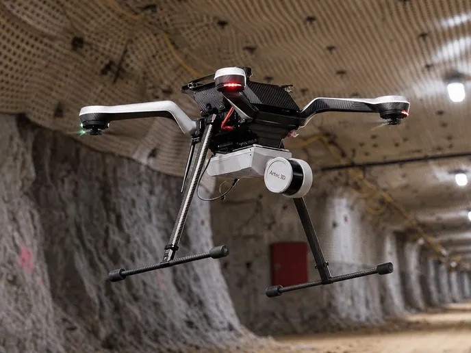
How do you inspect an ore pass without entering it?
Lower or fly a SLAM LiDAR scanner along it: walls are recorded at ±10 mm from tip to drawpoint, and a repeat scan shows wear and hang-ups at ±5 mm.
 From the tip or the drawpointLowered on a line or flown; nobody goes into the pass.
 Wall loss as a numberThis scan against the last, so wear has a depth and a rate.
 Hang-ups locatedThe blockage, its position and the geometry holding it, before anyone plans a shot.
 Short interruptionOne descent during a planned pause in tipping, not a shutdown.
Why ore pass wear is found late
An ore pass is inspected indirectly. Tipping stops, a light or a camera goes down, and someone judges the condition of walls that are dusty, dark and hundreds of metres long. Wear is uneven — it concentrates where the rock impacts on the bends and at the base of each leg — and a camera looking along the axis cannot tell whether a wall is 30 cm behind where it was or 3 m. The first hard evidence is usually a breakthrough into an adjacent excavation or a hang-up that will not clear.
The cost of finding it late is measured in the ore that cannot reach the shaft. An unplanned ore pass rehabilitation is a shutdown of the material handling system, with the alternative being a longer haul on the level. Knowing the wear rate turns that into a planned intervention, scheduled where the wall is thinnest and before it fails.
A scanner along the pass records the walls as a surface. Artec Jet, lowered from the tip or flown up from the drawpoint, holds ±0.03% positional drift with no GPS and records at ±10 mm in complete darkness. Compared with the previous scan in Artec Twins, wall loss shows at ±5 mm as a coloured surface with a depth; a hang-up shows as a shape with a position and the geometry that is holding it.
One pass, the whole length measured
The scan fits a planned pause in tipping.
 1. Stop tipping and rigJet on a line from the tip, or on a drone at the drawpoint, with the pass empty or at a known level.
- 2. Traverse and captureThe full length recorded at up to 1.9 million points per second with a 360° × 290° view, bends and legs included.
 3. Register to the levelsTwins ties the capture to the tip and drawpoint coordinates so every wear point has a true depth.
- 4. Compare with the last scanWall loss coloured by depth at ±5 mm; the wear rate per leg and per bend comes out of the difference.
 5. Plan the interventionThe wear map and any hang-up geometry into the planning package, with the rehabilitation scheduled where the wall is thinnest.
Which scanner for this work
A long, dark, vertical opening with abrasive walls: the device has to be small, sealed and independent of GPS and light.
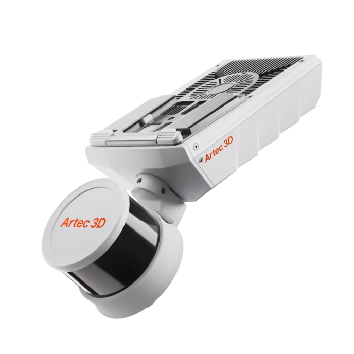
Artec Jet
- Best for
- The pass itself, lowered from the tip or flown from the drawpoint
- Type
- Multi-modal SLAM LiDAR
- Accuracy, up to
- ±10 mm underground, ±15 mm general
- Change detection
- ±5 mm
- Range
- 0.5–300 m
- Positional drift
- ±0.03%
- Deployment
- Handheld, backpack, pole, drone, vehicle, cage, robot
Jet’s 1.57 kg, IP65 rating and 16 hours of onboard capture make it the scanner that can be sent down an ore pass on a line or flown up one on a drone. It records the walls at ±10 mm with its own light and ±0.03% drift, and each scan overlays on the last at ±5 mm, which is what turns wear into a rate.
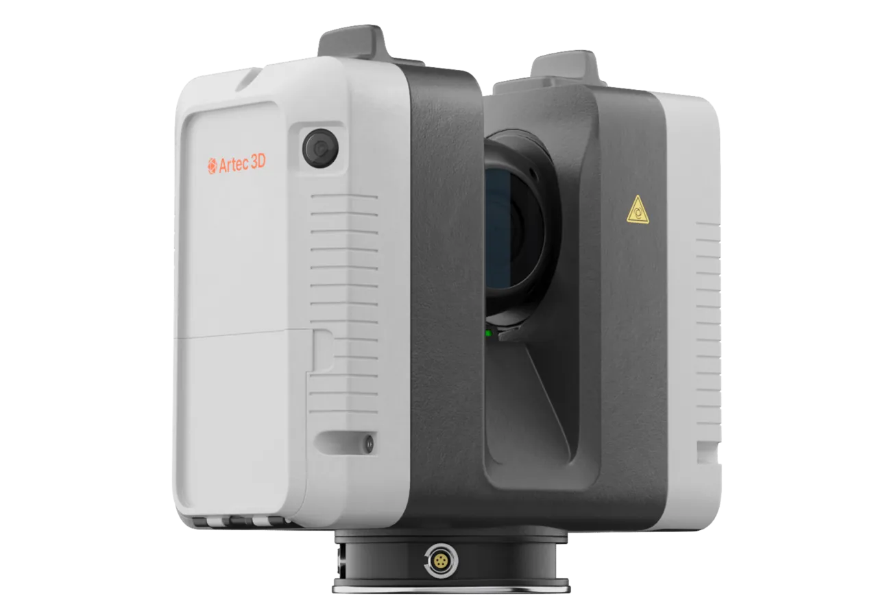
Artec Ray II
- Best for
- The tip and the drawpoint, and the visible section of the pass from either end
- Type
- Stationary long-range laser, tripod mounted
- Accuracy, up to
- 1.9 mm at 10 m, 2.9 mm at 20 m, 5.3 mm at 40 m
- Range noise
- 0.4 mm at 10 m
- Range
- 0.5–130 m
- Scan time
- 1 min 42 s at 3 mm, 10 m, without texture
- Field of view
- 360° × 300°
Where the pass cannot be traversed, Ray II on a tripod at the tip or the drawpoint records the visible section at 1.9 mm at 10 m in under two minutes — the brow, the first leg, the hang-up if it is in line of sight — and fixes the tip and drawpoint geometry the Jet traverse registers to.
See an ore pass scanned end to end during a tipping pause, with wall loss mapped against the last inspection — book a demo for your materials handling team.
Book a demoQuestions surveyors ask
Does the pass have to be empty?
It has to be clear along the section being scanned. A scan from the tip down to the muck level is still useful — the wear above the level is recorded — and a scan from the drawpoint up to a hang-up records the blockage and the geometry holding it.
How do we get a wear rate?
From two scans. Each records the walls at ±10 mm; overlaid in Artec Twins they show the difference at ±5 mm as a coloured surface. Divided by the tonnes tipped between them, that is a wear rate per leg, per bend and per metre.
Can it locate a hang-up we cannot see?
Yes. Flown or lowered to the blockage, the scanner records its shape, its position in the pass and the wall geometry around it, so the shot or the water can be planned against a measured target.
How much tipping time does a scan cost?
A traverse of the pass at capture speed and the time to rig the line or the drone. It fits a planned pause rather than a shutdown, and the processing happens afterwards, on surface.
Related applications
Tell us about the ore pass you inspect
Describe the pass — length, legs and bends, how it is inspected today and what has failed before. A mining specialist will come back with the deployment and what two scans of it would show.