
Mine shaft inspection and 3D scanning
A shaft inspection is a slow trip on top of the conveyance with a lamp and a notebook, looking at lining, buntons and guides as they go past. What gets written down is what someone saw; what gets measured is very little.
A scanner lowered or flown down the shaft records the whole barrel — every set, every metre of lining — as a measured surface, and the next inspection is compared against it.
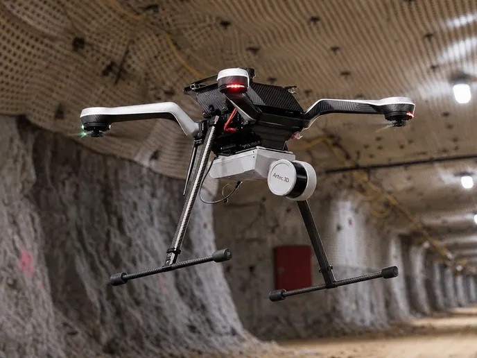
Can a shaft be inspected by 3D scanning?
Yes — lowered on the conveyance or flown, a SLAM LiDAR scanner records lining, sets and steelwork along the full depth at ±10 mm; repeat scans show movement.
 Nobody on the cage roofThe scanner rides the conveyance or flies; the inspector reads the model.
 The full barrel360° × 290° of view, so lining, buntons and guides are recorded together.
 Movement between inspections±5 mm change detection between one descent and the next.
 Measure any set laterBunton spacing, guide alignment or lining loss, taken from the model at the desk.
Why a shaft inspection records so little
A statutory shaft inspection is visual. An inspector rides the conveyance at reduced speed and notes what is seen: spalling in the lining, a bunton that looks corroded, water where it was not before. The record is a set of observations tied to approximate depths, and the comparison with the last inspection depends on the same person having looked at the same place in the same light.
Measurement in a shaft is harder still. Anything that has to be gauged — a guide out of alignment, a set that has moved, a section of lining that has lost thickness — means stopping the conveyance, working from its roof and measuring by hand in the one place on the mine where dropping a tool is a serious event. So most of what a shaft inspection reports is qualitative, and a trend is hard to prove.
A scanner on the conveyance or a drone records the whole shaft as it descends. Artec Jet holds ±0.03% positional drift with no GPS and no targets, so the capture stays true along the full depth, and its 360° × 290° field of view takes in lining, buntons, guides, pipes and cables in one pass at ±10 mm. Back on surface, every set can be measured from the model, and the next descent is overlaid on this one to show, at ±5 mm, what has moved.
One descent, the whole shaft measured
The scan runs at the conveyance’s inspection speed; nothing about the hoisting cycle changes.
 1. MountJet on the conveyance roof or a shaft-rated drone; no person rides with it.
 2. Descend and captureThe full barrel is recorded at up to 1.9 million points per second, lining to steelwork, in complete darkness.
 3. RegisterArtec Twins ties the capture to shaft collar and station coordinates so depths are true.
 4. Inspect at the deskBunton spacing, guide alignment, lining condition and inflow points, measured on the model rather than eyeballed from the cage.
- 5. Compare with last timeThe previous descent overlaid at ±5 mm; movement or loss shows as a coloured surface with a depth.
Which scanner for this work
A shaft is long, dark and vertical, which rules out anything that needs a tripod, GPS or light.
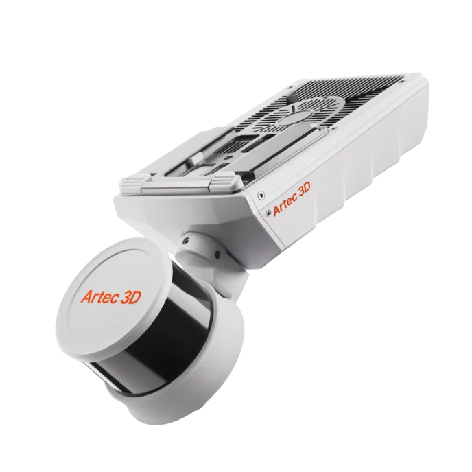
Artec Jet
- Best for
- Riding the conveyance or flown — lining, sets and steelwork along the full depth
- Type
- Multi-modal SLAM LiDAR
- Accuracy, up to
- ±10 mm underground, ±15 mm general
- Change detection
- ±5 mm
- Range
- 0.5–300 m
- Positional drift
- ±0.03%
- Deployment
- Handheld, backpack, pole, drone, vehicle, cage, robot
Jet is built for exactly this deployment: 1.57 kg, IP65, no GPS, its own light and about 16 hours of onboard capture, mounted to a conveyance or a drone. Its ±0.03% drift keeps a deep shaft true from collar to bottom, and 360° × 290° of view records lining and steelwork at once. Repeat descents overlay at ±5 mm.
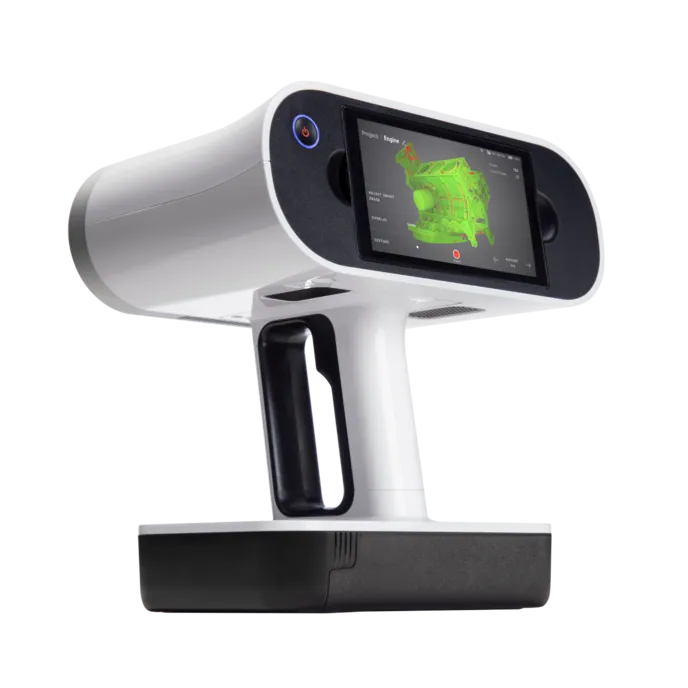
Artec Leo
- Best for
- Guide ends, bunton connections and lining defects at shaft stations and insets, at 0.1 mm
- Type
- Wireless handheld structured light, all-in-one
- 3D point accuracy, up to
- 0.1 mm
- 3D resolution, up to
- 0.2 mm
- Working distance
- 0.35–1.2 m
- Capture speed
- Up to 35,000,000 points/s in HD Mode
- Onboard
- 5.5″ touchscreen, processing and 512 GB — no laptop
At a shaft station or an inset, where a person can stand, Leo records a specific element — a guide joint, a bunton connection, a section of spalled lining — at 0.1 mm with colour texture, wirelessly. The detail registers into the Jet capture of the barrel so the defect has a depth and a dimension.
See a shaft recorded top to bottom on one descent, with every set measurable from the model — book a demo for your shaft engineer.
Book a demoQuestions surveyors ask
Does this replace the statutory visual inspection?
It gives the inspector a measured record to inspect against. What a regulation requires remains the regulation’s decision; what the scan adds is a complete, dated surface in which every observation has a depth and a dimension, and against which the next inspection is compared.
Can it capture a wet shaft?
Jet is IP65 and runs from −10 °C to +45 °C. Falling water and spray are within its rating; a scan will record inflows as features, with their depth, which is usually what the inspection wanted to know.
How does it stay accurate over hundreds of metres of depth?
SLAM positioning holds ±0.03% positional drift from the shaft geometry itself, and the capture is tied to collar and station coordinates in processing. That keeps depths true along the full barrel without any signal from surface.
What do we get for guide and bunton alignment?
The steelwork is in the model at ±10 mm, so guide straightness, bunton spacing and set-to-set offsets are measured from the data. Between two descents, ±5 mm change detection shows any set that has shifted.
Related applications
Tell us about the shaft you inspect
Describe the shaft — depth, lining, conveyance and what the last inspection struggled to measure. A mining specialist will come back with how the scanner mounts and what a descent would return.