
How accurate is 3D laser scanning for mining?
Accuracy is the first question and the most misread answer. A scanner’s accuracy is a distance error at a stated range, under stated conditions, and a figure quoted without the range is not a figure. The same instrument is 1.9 mm at 10 m and 5.3 mm at 40 m.
This page gives the numbers for each Artec scanner at the ranges a mine works at, explains what moves them, and says what each mining job actually needs — which is often less than the brochure figure and sometimes more.
How accurate is 3D laser scanning in a mine?
From a tripod, 1.9 mm at 10 m and 5.3 mm at 40 m; on the move underground, ±10 mm with ±5 mm change detection; by hand, 0.1 mm — each at its range.
 1.9 mm at 10 mTripod scanner; 2.9 mm at 20 m, 5.3 mm at 40 m. The range is part of the number.
 ±10 mm undergroundMoving SLAM scanner; ±15 mm on surface; ±0.03% positional drift.
 0.1 mm by handHandheld structured light at 0.35–1.2 m, for parts and components.
 ±5 mm changeTwo scans of the same surface compared — the figure monitoring runs on.
What moves the figure, and what each job needs
Three things set a scanner’s accuracy. Range: the laser beam spreads and the angular error projects further, so Artec Ray II’s 18-arcsecond angular accuracy is 0.87 mm at 10 m and proportionally more at 40 m. Positioning: a tripod scanner knows where it is; a moving scanner computes it, and Artec Jet’s ±0.03% drift is part of its ±10 mm — reset at every control point it passes. Registration: a survey is many captures aligned to each other and to mine grid, and the registration error at the joins and the residuals at control bound everything downstream. A volume across a bad join is wrong by the join, however accurate each scan was.
What each job needs is a different figure. Stope and heading reconciliation, profile against design and progress mapping run comfortably on ±10 mm. Convergence, slope and wear monitoring run on change detection — ±5 mm between two Jet scans, finer with Ray II from the same positions — because the comparison cancels much of the absolute error. An invoiced stockpile or a signed-off wall wants the tripod’s 1.9 mm at 10 m. A crusher mantle or a liner wants 0.1 mm, because the question is whether it seats. A shaft centre or a hoist alignment wants a single point right to the millimetre, which is a total station’s job, not a scanner’s.
The honest way to read a specification is to ask three questions: at what range, standing still or moving, and how was the survey tied to control. Ray II: 1.9 mm at 10 m, standing still, tied by targets or geometry. Jet: ±10 mm underground, moving, tied at control points with ±0.03% drift between them. Artec Leo: 0.1 mm at 0.35–1.2 m, handheld, registered to itself or to a CAD datum. Each is enough for its job and not for the next one’s, which is why a mine runs more than one.
How to verify accuracy on your own site
A figure you have checked on known references is yours; a brochure figure is the manufacturer’s.
 1. Pick known referencesSurvey control points and a measured distance — a pillar width, a bench height — established by your total station.
 2. Scan them as you would workFrom the tripod at working range; on the move along the drive; by hand on a gauge block or a part.
 3. Register and tieRegister in Artec Twins or Studio and tie to control; record the registration error and the residuals.
 4. Measure the referencesThe known distances and coordinates read from the model against their surveyed values.
 5. Write it downThe result, the range, the method and the date — the site’s own accuracy statement, repeated when anything changes.
Which scanner for this work
Three scanners, three accuracy figures at three ranges — which is the point.
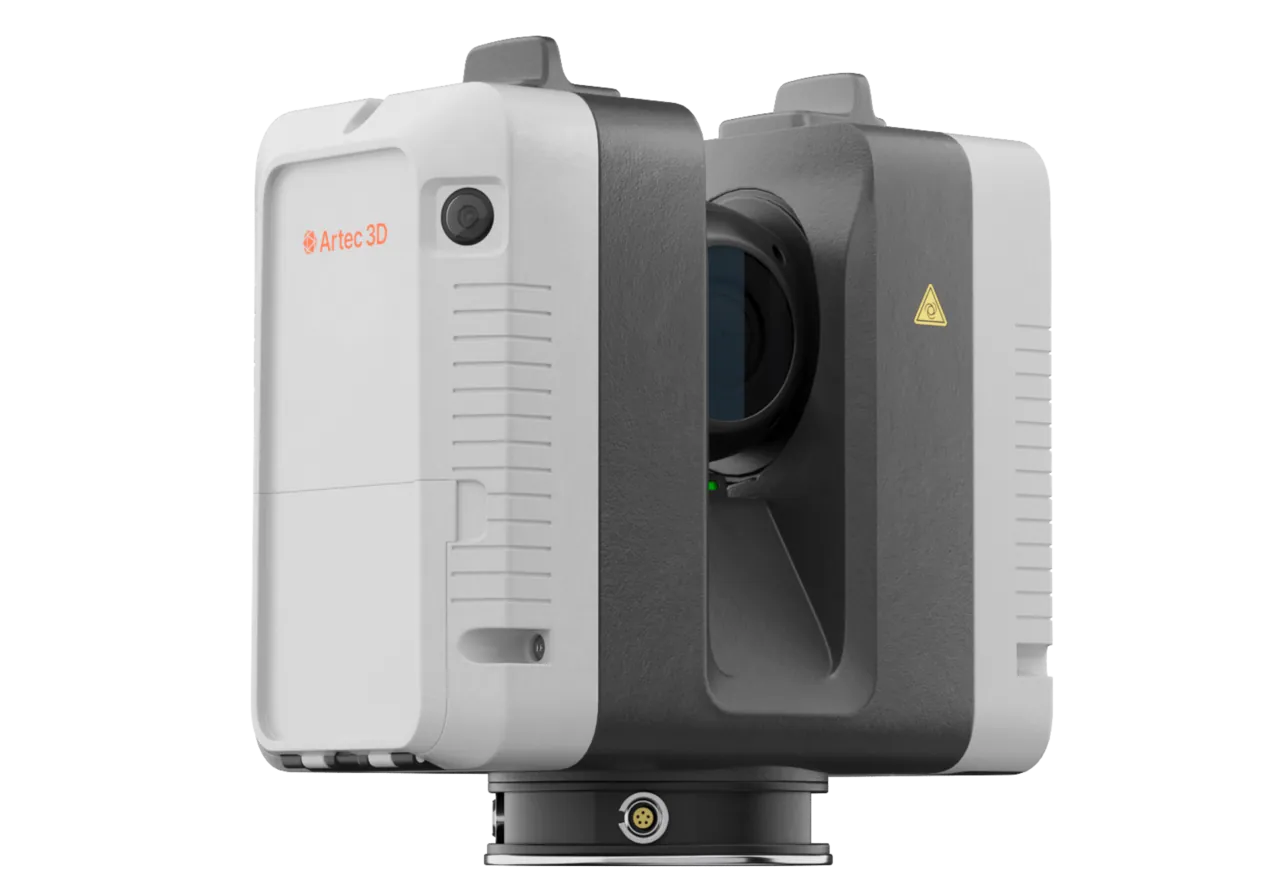
Artec Ray II
- Best for
- The survey-grade figure — walls, stockpiles, plant, machines from a tripod
- Accuracy, up to
- 1.9 mm at 10 m, 2.9 mm at 20 m, 5.3 mm at 40 m
- Angular accuracy
- 18″, equal to 0.87 mm at 10 m
- Range noise
- 0.4 mm at 10 m
- Range
- 0.5–130 m
Ray II is 1.9 mm at 10 m, 2.9 mm at 20 m and 5.3 mm at 40 m, with 18″ angular accuracy and 0.4 mm range noise at 10 m; range 0.5–130 m. Because it stands still, its accuracy is the instrument’s, and it is the reference surface the rest of a mixed survey registers against.
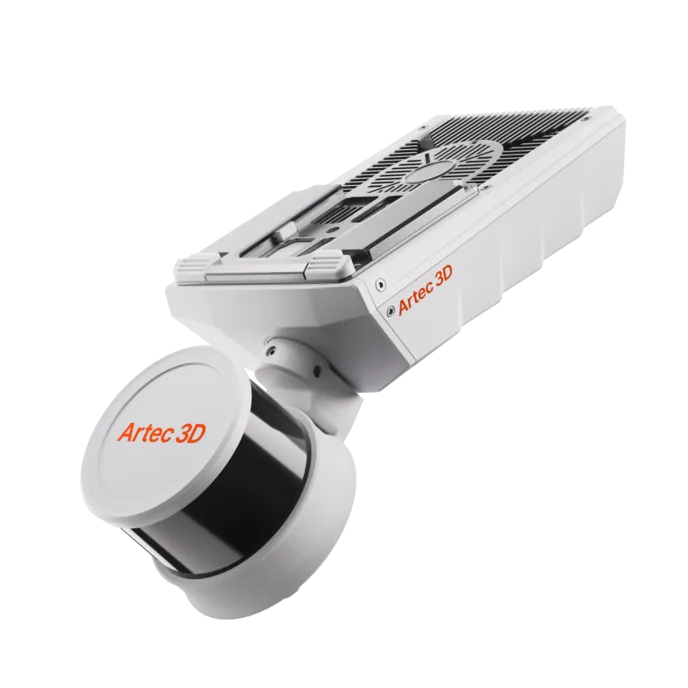
Artec Jet
- Best for
- The moving figure — headings, voids, roads, on the move
- Accuracy, up to
- ±10 mm underground, ±15 mm general
- Change detection
- ±5 mm
- Positional drift
- ±0.03%
- Range
- 0.5–300 m
Jet is ±10 mm underground and ±15 mm on surface, with ±0.03% positional drift and ±5 mm change detection between scans. Because it moves, its accuracy includes knowing where it was, and control points reset the drift; between them SLAM holds it.
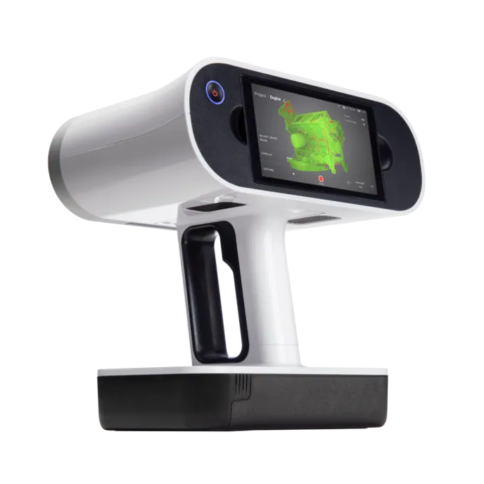
Artec Leo
- Best for
- The component figure — parts, liners and mounting points by hand
- 3D point accuracy, up to
- 0.1 mm
- 3D resolution, up to
- 0.2 mm
- Working distance
- 0.35–1.2 m
Leo is 0.1 mm 3D point accuracy and 0.2 mm resolution at a working distance of 0.35–1.2 m. The range is short, so the figure is fine; it is the accuracy that decides whether a mantle seats or a bracket fits, and Element holds under 0.1 mm per 1000 mm on crusher parts with it.
See the accuracy checked on your own control points, at your own working ranges, and written down — book a demo for your survey manager.
Book a demoQuestions surveyors ask
Why does the same scanner have three accuracy figures?
Because accuracy is a function of range. Ray II is 1.9 mm at 10 m, 2.9 mm at 20 m and 5.3 mm at 40 m: the beam spreads and the angular error projects further with distance. A single figure without a range is not a specification.
Is ±10 mm on the move good enough?
For stope and heading reconciliation, profile against design, progress and change detection at ±5 mm, yes. For an invoiced stockpile volume or a signed-off wall, use the tripod scanner’s 1.9 mm at 10 m. The two register into one model.
How does registration affect accuracy?
It bounds it. Each scan is accurate to its figure; the survey is accurate to the registration error at the joins and the residuals at control. Those numbers are recorded in Artec Twins and should travel with the dataset.
Can we validate the accuracy ourselves?
Yes, and you should: scan your own control points and a known distance at working range, tie to control, and compare. The steps are on this page; the result is the site’s own accuracy statement.
Related applications

Tell us what accuracy your jobs actually need
Describe the jobs, the ranges you work at and the figures you have to defend. A mining specialist will come back with which scanner meets each one and how to verify it on your control.